20+ entity diagram software
The objects are further explained below. Student Score - Ternary Relationship.
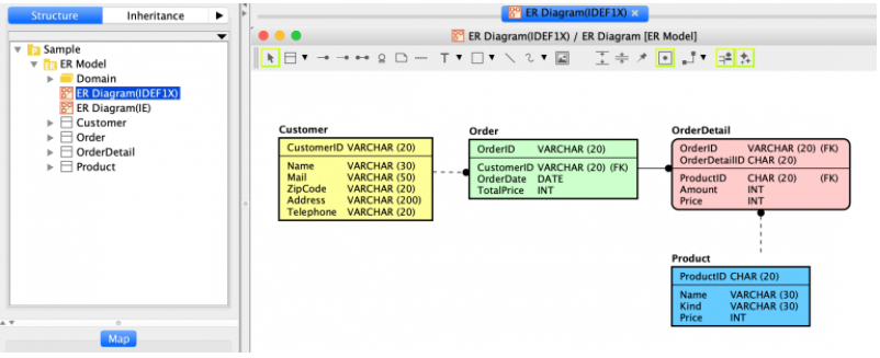
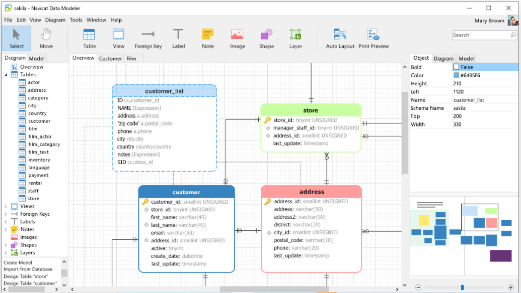
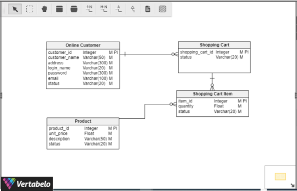
What S The Best Er Diagram Tool For Oracle Vertabelo Database Modeler
As you click on the Edit Link or Open link from the submenu the Visio tool launches and the diagram opens.
. Often used in the plural to suggest situations where a piece of software may be useful. Gleek gives developers a powerful tool to create not only UML diagrams but also flowcharts entity-relationship diagrams and much more. It is called a star schema because the entity-relationship diagram between dimensions and fact tables resembles a star where one fact table is connected to multiple dimensions.
It is often used as the basis for data flow diagrams or DFDs as they are commonly known. My Top Picks for Online Entity Relationship Diagram Tools 1. Use case diagrams consist of 4 objects.
Give gleekio a spin and leave cumbersome mouse-clicking behind. EdrawMax is one such process flow diagram software that lets you import Visio process flow diagrams so you. It supports these databases.
Cardinality can be of different types. It was developed to reflect more precisely the properties and constraints that are found in more complex databases such as in. Entity relationship diagrams in software engineering.
Entity relationship diagrams are used in software engineering during the planning stages of the software project. Now you can edit the diagram or view it. This could be a person organization or an external system and usually drawn like skeleton shown below.
To modify the Visio diagram you have pasted or inserted in the Word file select the Visio diagram and then go to the Linked Visio Object present in the context menu. Dia is roughly inspired by the commercial Windows program Visio though more geared towards informal diagrams for casual use. They help to identify different system elements and their relationships with each other.
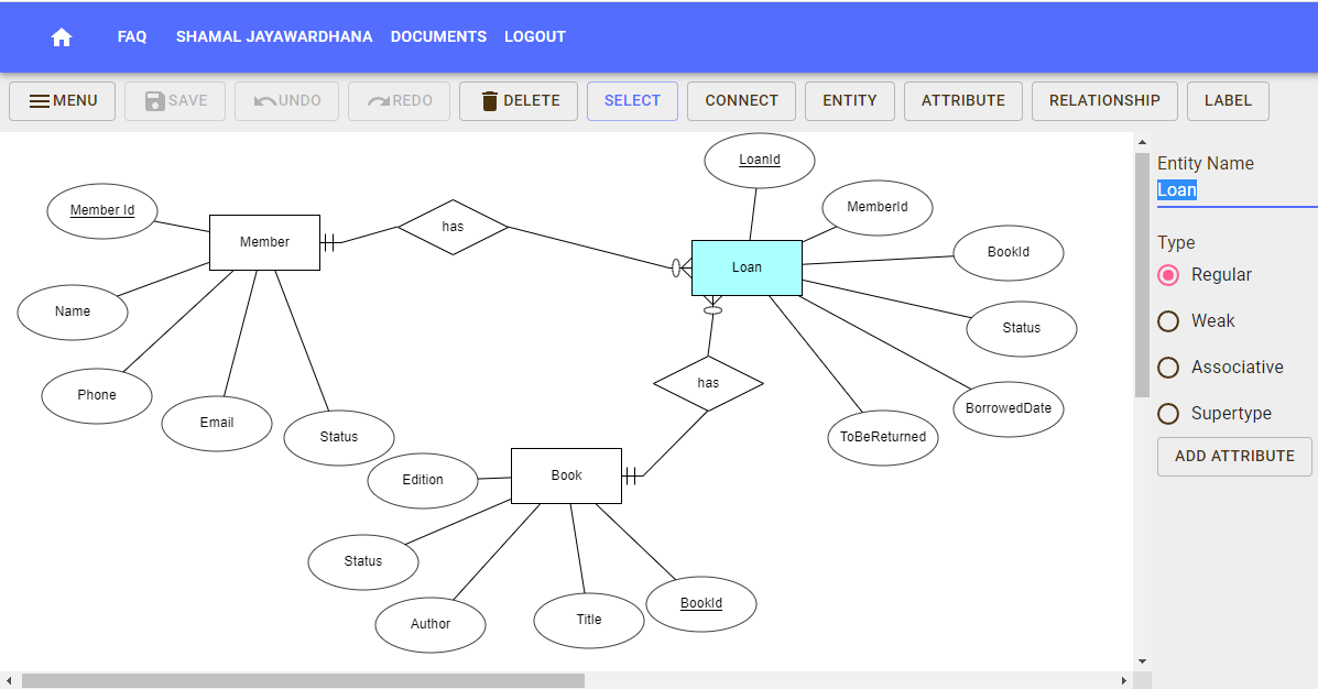
How do we create a Class diagram for a Library Management system. Lets compare the features of a few top-rated ER diagram online tools and see how they support database design. 20 1500 Languages 98 11 English French German Japanese Spanish Italian Portuguese Russian Korean Simplified Chinese Traditional Chinese.
This is the next installment in a series of articles about the essential diagrams used within the Unified Modeling Language or UML. In my previous article on sequence diagrams I shifted focus away from the UML 14 spec to OMGs Adopted 20 Draft Specification of UML UML 2In this article I will discuss Structure Diagrams which is a new diagram. Data Flow Diagrams are used to represent the flow of data as well as the processes and functions involved to store manipulate and distribute data among various components of the system and between the system and the environment of the system by a specific set of graphical representations.
An ERD visualizes the relationships between entities like people things or concepts in a database. ERD stands for entity relationship diagram. One to one When each entity in each entity set can take part only once in the relationship the cardinality is one to oneLet us assume that a male can marry to one female and a female can marry to one.
Provide structure before coding begins Visualize requirements as you build on existing work. It shows the detailed Process Flow Diagram of the Crude Oil Distillation Unit. With the help of a data flow diagram your software team can.
On the ARPANET the starting point for host-to-host communication in 1969 was the 1822 protocol which defined the. Actor in a use case diagram is any entity that performs a role in one given system. In contrast to typical federated identifiers DIDs have been designed so that they may be decoupled from centralized registries.
Use Case Diagram objects. Capture the increasingly complex flow of information through a system with a data flow diagram. A successful application diagram contains a lot of information the ownerclient knows and likes to see and does not know and does not like to see because of the.
An experienced user spent 20 minutes creating this. A usage scenario for a piece of software. DW ETL 20 Software Mobile Apps Testing 15 Training.
Decentralized identifiers DIDs are a new type of identifier that enables verifiable decentralized digital identity. A potential scenario in which a system receives an external request such as user input and responds to it. It currently has special objects to help draw entity relationship diagrams UML diagrams flowcharts network diagrams and many other diagrams.
A DID refers to any subject eg a person organization thing data model abstract entity etc as determined by the controller of the DID. The enhanced entityrelationship EER model or extended entityrelationship model in computer science is a high-level or conceptual data model incorporating extensions to the original entityrelationship ER model used in the design of databases. This sample was created in ConceptDraw DIAGRAM software using the process flow diagram symbols from the libraries of Chemical and Process Engineering Solution.
The center of the star schema consists of a large fact table and it points towards the dimension tables. It also depicts the logical flow of information in a. In Dragon1 we use a solid line to indicate currently an entity is there a dotted line to indicate an entity was there a dashed line to indicate an entity will be there in the future.
Developers and engineers use these diagrams as a framework to support their work in many ways. In software and systems engineering the phrase use case is a polyseme with two senses. One of the first uses of the term protocol in a data-commutation context occurs in a memorandum entitled A Protocol for Use in the NPL Data Communications Network written by Roger Scantlebury and Keith Bartlett in April 1967.
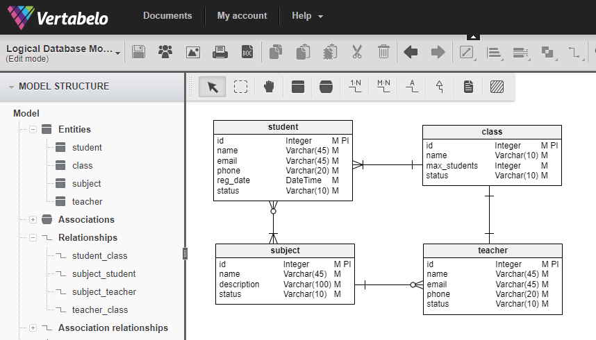
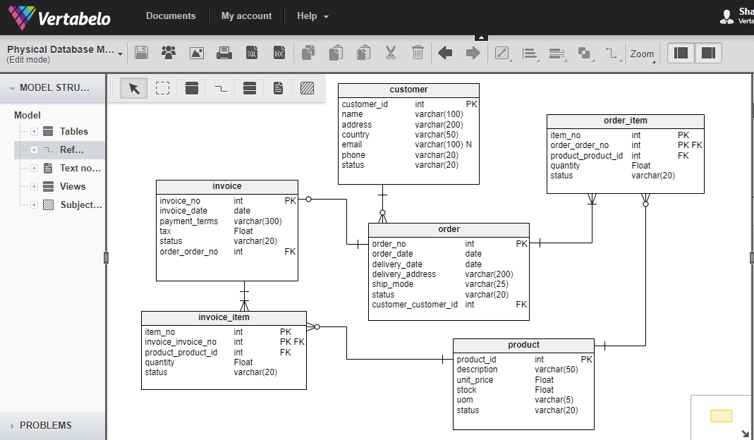
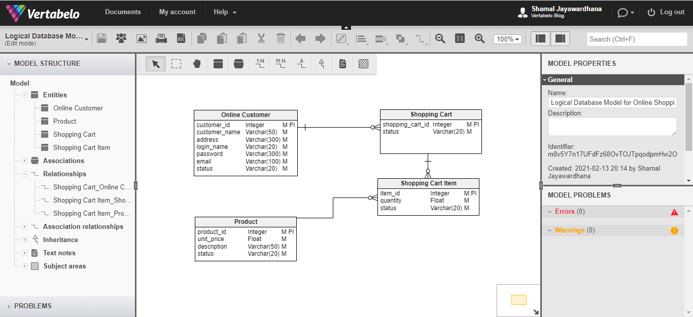
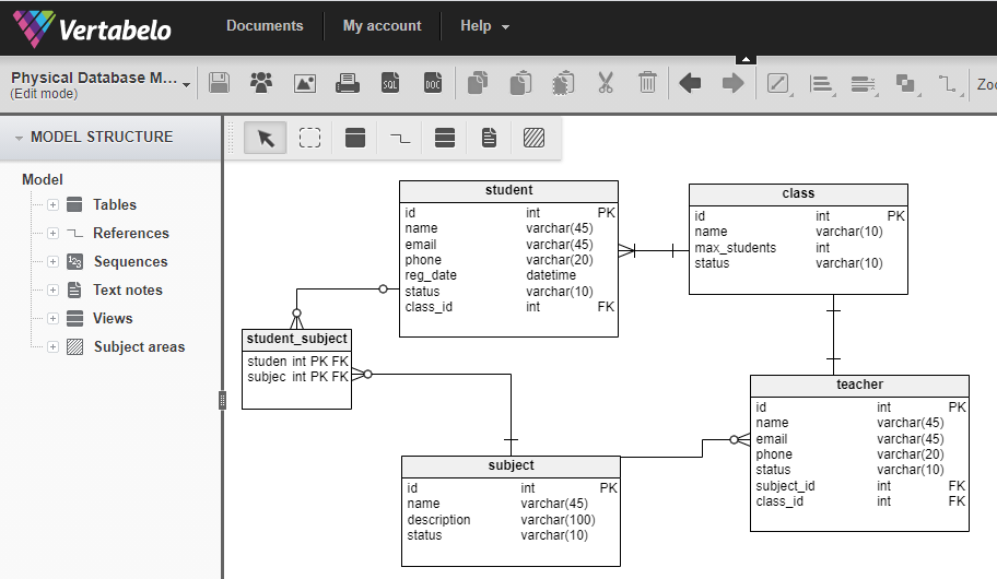
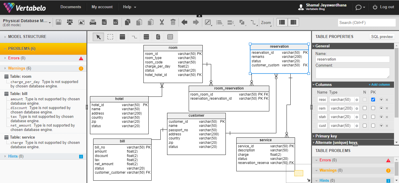
The number of times an entity of an entity set participates in a relationship set is known as cardinality. It can be used to draw many different kinds of diagrams. Vertabelo is a professional database modeling tool that lets you design a data model collaboratively in the browser.
People also call these types of diagrams ER diagrams and Entity Relationship Models. Entity Relationship Diagram ERD and UML Diagram Only Professional Available. Process Flow Diagram Crude Oil Distillation Unit.
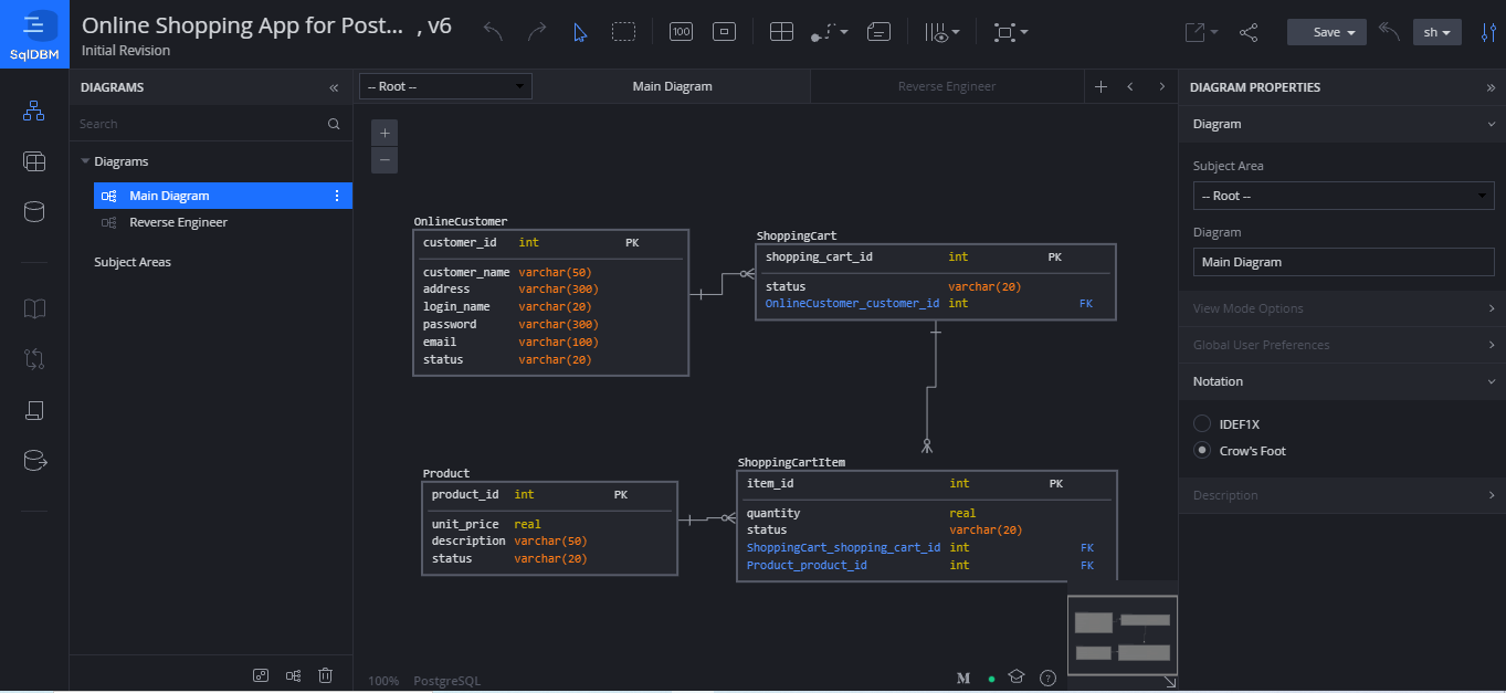
What Erd Tools Can I Use To Create An Er Diagram Vertabelo Database Modeler
What Erd Tools Can I Use To Create An Er Diagram Vertabelo Database Modeler

Making Entity Relationship Diagrams Erd Easier To Understand Mastering Requirements And Solution Envisioning For Microsoft Business Applications
What Erd Tools Can I Use To Create An Er Diagram Vertabelo Database Modeler
What To Look For In Your Er Diagram Tool Vertabelo Database Modeler
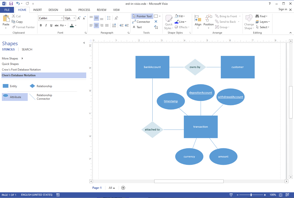
How To Create An Er Diagram In Visio Edrawmax
What Erd Tools Can I Use To Create An Er Diagram Vertabelo Database Modeler
What To Look For In Your Er Diagram Tool Vertabelo Database Modeler

Making Entity Relationship Diagrams Erd Easier To Understand Mastering Requirements And Solution Envisioning For Microsoft Business Applications
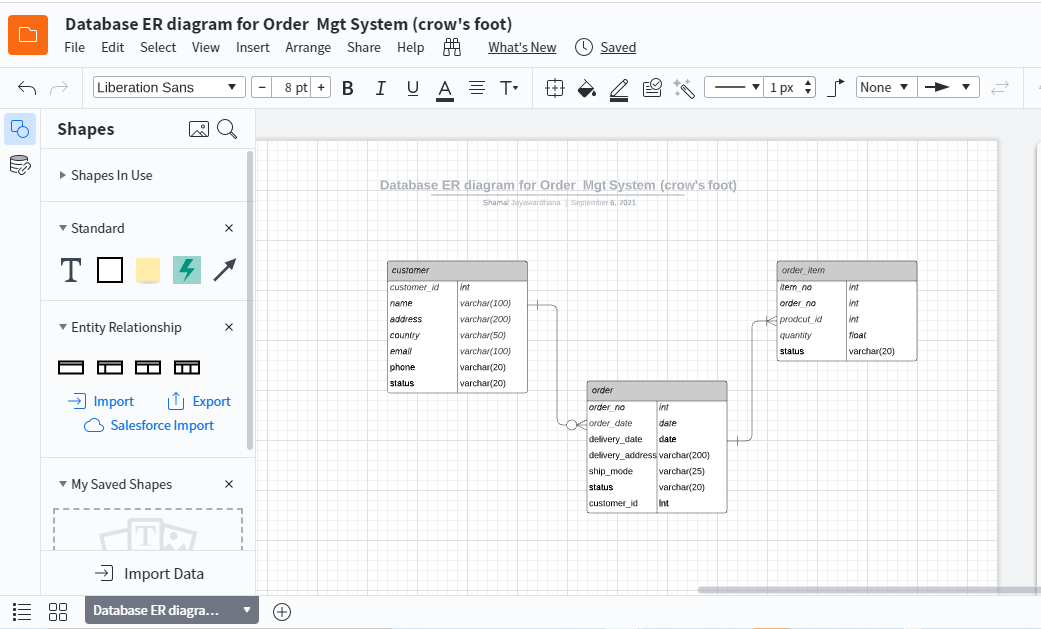
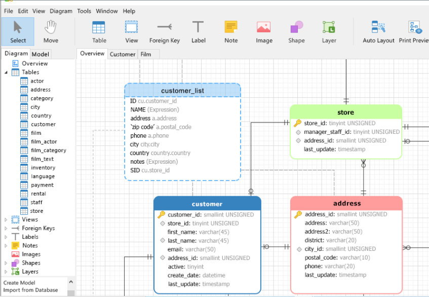
Online Or Desktop Er Diagram Tool Vertabelo Database Modeler
What S The Best Er Diagram Tool For Oracle Vertabelo Database Modeler
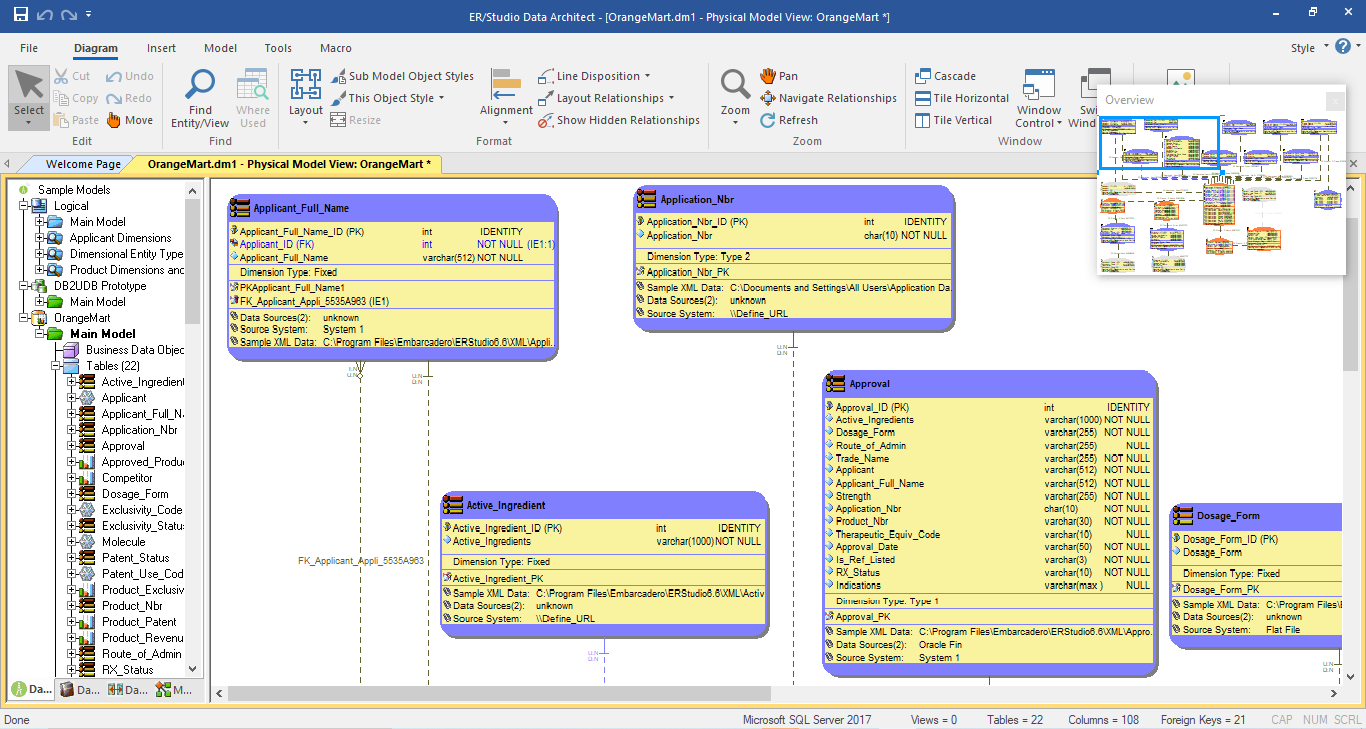
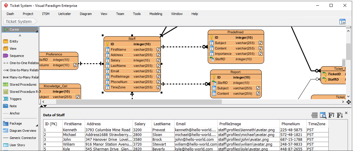
What S The Best Er Diagram Tool For Sql Server Vertabelo Database Modeler
What S The Best Er Diagram Tool For Sql Server Vertabelo Database Modeler
What S The Best Er Diagram Tool For Sql Server Vertabelo Database Modeler
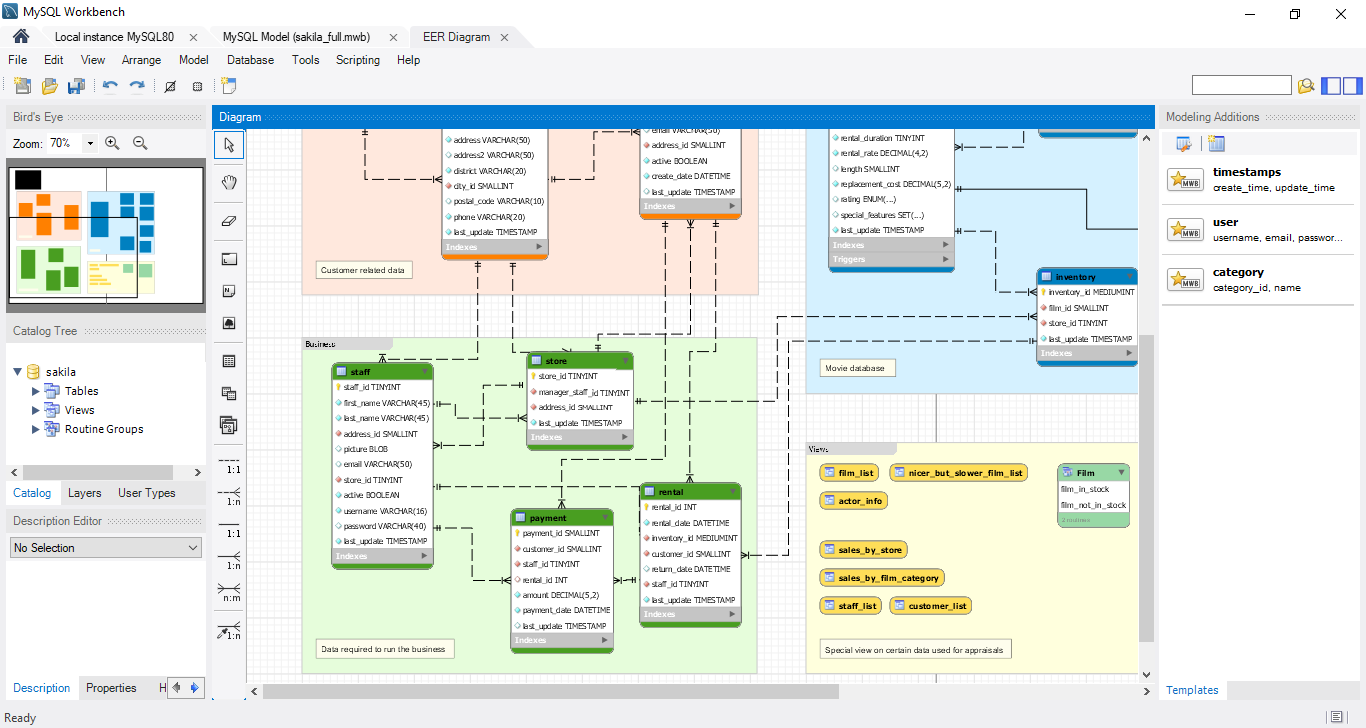
Online Or Desktop Er Diagram Tool Vertabelo Database Modeler
Online Or Desktop Er Diagram Tool Vertabelo Database Modeler
What Erd Tools Can I Use To Create An Er Diagram Vertabelo Database Modeler